 |
|

[Disassemble
notes]
|disassemble:Vivante
SE|
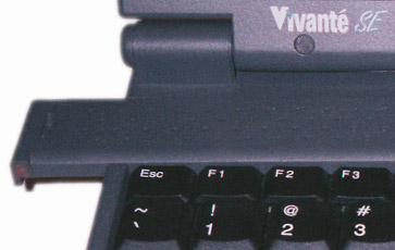
[!]Vivante
SE: fixing loose AC connector.
[-]Keep
in mind that you are operating at Your Own
Risk !
1.Take all the screws out
from the bottom.
2. Remove the keyboard
(see notes below).
3. Let the screen open up,
until it lays on the table, you might want to put a book underneath it.
4. We have to completely
remove the screen, 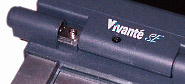 so look at the two sides where the screen is attached to the laptop. Do
you see that word VIVANTE on the bottom of the screen? Just to the left
there is this cap that you can just slide to the left. You might
want to use to force here. Also, do the same to the cap on the right side
of the screen.
so look at the two sides where the screen is attached to the laptop. Do
you see that word VIVANTE on the bottom of the screen? Just to the left
there is this cap that you can just slide to the left. You might
want to use to force here. Also, do the same to the cap on the right side
of the screen.
5. Underneath these caps
you see four (clear) screws. Just take them out! The screen will come of.
6. The place where you took
the keyboard from there is (was) a metal HEAT plate. Underneath it (you
have to remove it) you see the connectors from the screen, take these out
too!
7. The keyboard and touchpad
are both connected to the laptop with a connector. Pull the connector,
NOT the cable! When you pull it just a little, the cable comes loose. Carefully!
8. Remove the harddrive,
by pulling it towards you. That's easy.
9. Now the FUN PART!!! Take
all the screws out that you can see. Memorize where you got them from.
10. When this is done, you
can go ahead by take the top of the laptop. You might want to use some force again. I took a knife and pushed at all
sides of the laptop.
You might want to use some force again. I took a knife and pushed at all
sides of the laptop.
11. Just look closely how
the both parts are connected.
12. Finished? drink some
coffee, walk the dog or something ;-)
13. The motherboard is only
attached to the bottom with 4 screws if I remember correctly.
14. Now, the place where
the harddrive use to be is somewhat relentless to let go, so use the knife
to detach the motherboard from the bottom plate.
15. Okay, I think by now
the board is completely loose, and you can take a
look at the connector.
16. My connector got loose
on the GROUND-side of it. Just some cracks in the
solder, nothing big.
17. Solder the joints....
And then re-assemble ;-)
[!]Vivante
SE: Replacing/adjusting keyboard.
[-]Keyboard
is attached to the board via ribbon cable, and the connector is kind of
loose i.e. if it's shifted slightly you may experience some faults usually
with side keys.
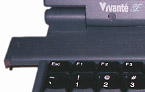 To
get aquainted with your keyboard you may gently slide to the left
the plastic lid (the one with a small holes in the upper part of the keyboard)
and curiously but GENTLY lift and slide the keyboard plate but DO NOT PULL
IT OUT since the flat wire connector is kind of loose). To
get aquainted with your keyboard you may gently slide to the left
the plastic lid (the one with a small holes in the upper part of the keyboard)
and curiously but GENTLY lift and slide the keyboard plate but DO NOT PULL
IT OUT since the flat wire connector is kind of loose). 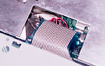 The flat wire goes in the bottom of the keyboard plate, so you should be
able to keep the keyboard plate standing upright on its bottom edge right
in place without extracting the flat wire. Then you will see how it's connected
to the board.
The flat wire goes in the bottom of the keyboard plate, so you should be
able to keep the keyboard plate standing upright on its bottom edge right
in place without extracting the flat wire. Then you will see how it's connected
to the board.
IF YOU'RE NOT SURE IN YOUR
HANDS DON'T DO IT BY YOURSELF, because if you extract the flat wire you
disconnect your keyboard. Yes, it's so easy beacuse it's meant to be so
in order to change keyboard quickly, but if you don't have such experience
you will spend some time connecting it back. In your case you want to just
press it LIGHTLY down holding the wire close to the connector on
board.
After that close everything
in opposite order.
|disassemble:Vivante
XL|
[!]Below
are the steps you can follow to locate your CMOS battery. Keep in mind
that you are operating at Your Own Risk
if you follow these steps. Before doing so, make sure you look in the RAM
compartment on the bottom of your Vivante
XL to see if your CMOS battery can be seen.
[-]First,
remove the speaker assembly:
1. Remove the keyboard.
2. Using something like
an Exacto knife, cut a small square in the "Vivante XL" label found
on the speaker cover. Cut the square under the "X". The grill covering
the speakers already has a small hole there.
3. Using a philips screwdriver,
loosen the screw found at the bottom of the newly formed hole.
4. There is a black piece
coming from the center of speaker assembly with a screw holding it in place.
Remove that screw.
5. The speaker assembly
should now lift up.
The CMOS battery is at the
top near the screen above the F9 and F10 keys.
Unfortunately there are
a lot of screws that have to be removed before that plastic can be lifted.
Keep good track of the screws as you remove them.
1. Unplug the two connectors
that go to the screen.
2. Remove the screen's hinge
covers.
3. Remove the hinge screws
and set the screen to the side.
4. Go around the outside
of the case and start removing screws starting with the two that you uncovered
by removing the screen. The top part of the case is easy to remove. There
are a few places where it snaps into place but it is still easy to remove.
If you are having a hard time getting it to pop off, look for more screws
to remove.
Once the top of the case
is off, the CMOS battery is standing upright near the top left corner of
the floppy drive (if you have one).
|disassemble:Vibrant
|
[!]Vibrant:
Reseating modem.
[-]If
the BIOS setting is set to modem, but the modem fails diagnostics (and
you feel brave), you can try re-seating the modem. All it entails is sliding
the top plastic piece above the keyboard to the right and removing it.
Carefully lift up the keyboard, becareful not to pull out the keyboard
ribbon cable. You should see a metal plate with 2 or 3 screws in it. Remove
the screws. Once the place is removed, you should see the modem on the
left side. It looks like a green circuit board about 2" x 2". It should
have a black sponge-like pad on the right side. Push down on the pad.
If you feel it move down
a little, then this was the problem. Put everything back together and you
should be ok.
|